

Silicom IS100 40/100G Bypass Switch|TAP
◆Supports SR4, LR4, and BiDi optical interfaces
◆Supports ER4 and CWDM4 optical interfaces
◆Two on Board Watch Dog Timer (WDT) Controllers
◆Monitors inline appliance latency status
◆Enables flexible customization of Heartbeat packets for advanced monitoring control
◆Automatically switches to TAP mode upon heartbeat delay detection to prevent link flapping
◆Configurable heartbeat recovery delay for precise failover control
◆Local and remote log,SNMP v1/2/3
◆Swappable modules with independent power control
◆Full line-rate performance with zero packet loss
-
Inline security tools such as NGFW, IPS, WAF, DDoS, SSL, and DPI systems act as the first line of defense against cyberattacks, worms, and other intrusions.
These devices must deeply inspect every packet to verify its safety before allowing it to pass, a process that requires significant CPU resources and close coordination between hardware and software. However, the performance of these security appliances often depends on the complexity and number of their inspection rules—meaning that the actual throughput is rarely equal to the interface speed. As a result, occasional system crashes or instability during software updates can cause unexpected network outages, leading to immediate business disruption and even direct revenue loss.
A Bypass Switch mitigates this risk by ensuring that network connectivity is maintained even when inline devices fail. From a protection standpoint, Bypass Switches can be categorized into three levels:- Standard:Switches to bypass mode when the inline device or the switch itself loses power.
- Advanced:Includes standard features plus automatic bypass during inline device failure or disconnection.
- Ultimate:Adds full self-monitoring capabilities, enabling bypass even if the Bypass Switch itself crashes or loses power.
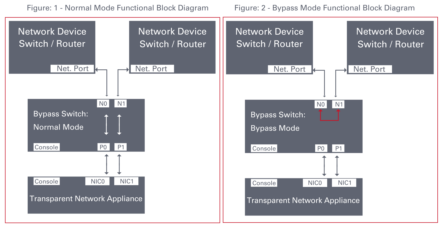
1. In Normal Inline mode, the IS100 directs live network traffic through the connected inline security or performance monitoring appliance.
The IS100 100G Bypass Switch delivers ultimate-level protection, featuring both active and passive bypass capabilities to safeguard network uptime during device maintenance, system crashes, or power outages.
It not only transmits heartbeat packets to monitor the health of inline security appliances but also performs self-health monitoring.
If the switch itself fails or loses power, it automatically enters bypass mode—ensuring uninterrupted network service and eliminating any single point of failure.
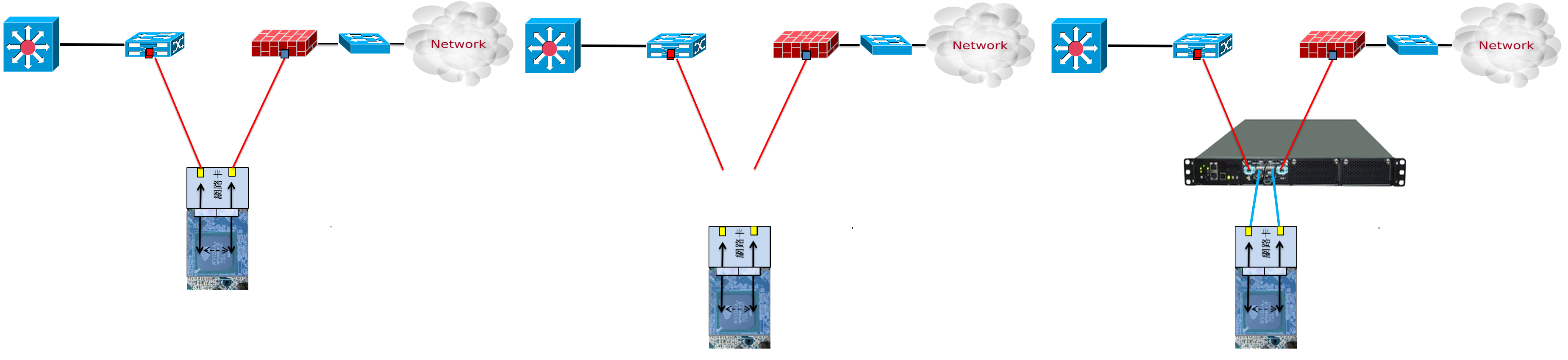
A common misconception among users is that inline security devices equipped with bypass-capable NICs can prevent network downtime during device failures. In reality, the most frequent cause of outages in IPS, WAF, DAM, or bandwidth management systems operating in inline mode is not just hardware failure—but system crashes or devices entering a “half-dead” state, where performance severely degrades without a complete disconnection. This often results in packet loss, application failure, or total loss of connectivity.
Even in HA (High Availability) environments, such failures typically require manual intervention—engineers must physically isolate the malfunctioning inline device before traffic can properly fail over to the secondary unit.
While a bypass-capable NIC can allow traffic to flow only when the device is powered off, it does not provide true automated failover protection. As a result, businesses still experience service interruptions and downtime before the issue is resolved.
Recognizing these challenges, more organizations are now prioritizing advanced link protection mechanisms and investing in intelligent bypass solutions that deliver fully automated failover and ensure continuous network availability—without manual intervention or downtime.
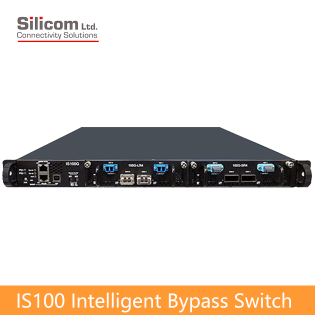
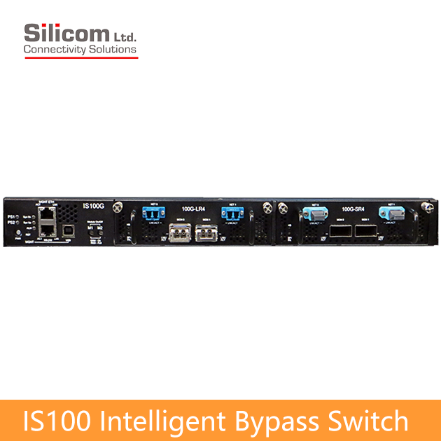
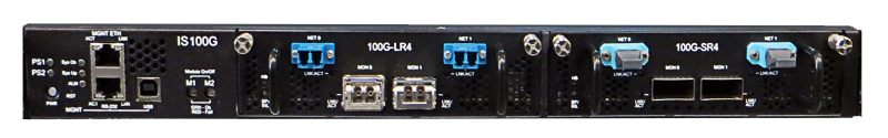
The Silicom IS100 Intelligent Bypass Switch is built in a standard 1U chassis and features two modular expansion slots. Each 100G module supports one pair of bypass ports (1 segment).
The IS100 Intelligent Bypass Switch supports both single-mode fiber (100GBase-LR4) and multi-mode fiber (100GBase-SR4 / SR10) standards, providing flexibility for various deployment needs.
Each bypass module includes two MPO/LC network ports for connecting the upstream and downstream network links, and two QSFP28 ports for attaching inline security appliances operating in inline mode.
The Silicom IS100 Intelligent Bypass Switch supports four operating modes:
Normal Inline, Bypass, TAP (Traffic Access Point), and Linkdrop mode.
2. In Bypass mode, the IS100 stops forwarding traffic to the connected inline appliance and instead routes packets directly back to the network, maintaining continuous data flow even when the inline device is offline.
3. In TAP mode, traffic passes transparently between the NET ports, while being replicated to the MON ports for monitoring or analysis.
Traffic entering NET0 is copied to MON0, and traffic entering NET1 is copied to MON1.
The actual production traffic flows only between NET0 and NET1, ensuring that the connected monitoring devices on MON0 and MON1 do not interfere with the live network—allowing engineers to analyze real-time traffic non-intrusively for diagnostics and troubleshooting.
4. In Linkdrop mode, the IS100 automatically detects a failure or crash on the connected inline device and shuts down the network ports (NET0, NET1).
This controlled disconnection allows traffic to fail over seamlessly to the backup device in an HA (High Availability) configuration, ensuring true always-on, automated network protection.
The IS100 bypass module generates Heartbeat packets that travel along the live network path to the inline monitoring appliance.
These Heartbeat packets enter the appliance through its network ports and are bridged internally together with other network traffic before being sent out through the opposite port—creating a continuous verification loop. If the IS100 module detects the return of the Heartbeat packets within the predefined interval, it confirms that the inline device is operating normally and maintains the current inline mode.
If the IS100 bypass module fails to detect the return of Heartbeat packets from the inline device within the configured timeout period,
the system automatically switches to one of the predefined modes — Bypass, TAP (Traffic Access Point), or Linkdrop — depending on user configuration.
When the inline monitoring appliance resumes normal operation and the Heartbeat packets are detected again within the preset interval,the IS100 automatically restores the Normal Inline mode.
Typically, the Bypass mode is triggered in cases of power failure, link failure, system crash of the inline software application, or when manually activated by the user for maintenance or troubleshooting purposes.
The IS100 features a dual bypass safety architecture designed by Silicom to ensure continuous network protection. This architecture is based on two independent bypass routing circuits — one active and one passive.
If the system detects a failure in the active bypass routing path, it automatically switches to the passive bypass route.
As a result, the IS100 not only monitors the health of the connected inline appliances, but also verifies the integrity of its own bypass functionality, providing an extra layer of reliability and assurance to users.
The IS100 can be configured and managed through the following methods:
1. Simple CLI commands via serial console, Telnet, or SSH
2. Web-based graphical user interface (GUI)
3. SNMP Write for automated configuration through network management systems
The IS100 is a 1U rack-mount system that supports up to two 100G bypass modules.
It equipped with dual redundant 110–220V AC power supplies or optionally with dual redundant -48V DC power inputs.
-
- Self generating heartbeat pulses – No driver or management port is required to generate pulses.
- Sets to Bypass when it detects in-line system failure.
- Sets to Bypass when it detects in-line system link failure
- Sets to Bypass when it detects in-line software application system hang
- Sets to Bypass on Power failure
- Sets to Normal when it detects in-line system recovery.
- Double Safe Bypass architecture with two routing circuitries.
- Centralized managements
- Two on Board Watch Dog Timer (WDT) Controllers.
- Software programmable time out interval.
- Software Programmable WDT Enable / Disable.
- Independent Bypass / Normal / Tap /Linkdrop operation in every module.
- Supports up to two 100G Bypass segment in a 1U chassis.
- Supports TAP mode of operation.
- Simple CLI configuration management via serial port.
- Telnet management interface via network management port.
- SSH management interface via network management port.
- Supports SNMP version 1, 2c, 3 (SHA, AES)
- Supports remote log
- Supports TACACS+
- Supports RADIUS
- Supports NTP
- Supports time zone
- Supports multi configuration backup
- Support Two ports link feature – if one of the network ports link fails it will drop the link on the other network port as well.
- Two redundant power supplies
- Optional -48V DC power supplies
-
IS100 Bypass Switch
Silicom 100G Intelligent Bypass Switch
Bypass Switch Specifications WDT Interval (Software Programmable): Routing
Transmit heart beat packet every 3mS – 10Sec. Default 5mS
Verification packets received every 10mS – 50Sec. Default 20mSec
Double Bypass
Transmit heart beat packet every 300mS – 60Sec. Default 7Sec
Verification packets received every 1S – 253Sec. Default 20SecProduction Default configuration Mode at Power up: Bypass Heartbeat: Activated Bypass Switch is ready and in-line device responds to heartbeat: Change to Normal In-line device responds to heartbeat: Normal In-line device does not respond heartbeat: Bypass Mode at Power 0ff: Bypass Heartbeat Packet: Internetwork Packet Exchange IS1001U: Bypass Switch 1U Host System Technical Specifications Dockings: Front holders Voltage Input: AC: 90-240 VAC Auto-Select
-48 (-75 – -36) VDCPower Consumption: With no module : 240W
With one LR4 module (with 90% utilization):405W
With 2 LR4modules (with 90% utilization):552WSize: 435mm x 586 mm x 44 mm ( 17.12” x 23.07” x 1.732”)
Wide x Depth X HeightWeight: 10Kg Operating Humidity: 0%–90%, non-condensing Operating Temperature: 0°C – 40°C (32°F – 104°F) Storage Temperature: -20°C–65°C (-4°F–149°F) EMC Certifications: Class B FCC / CE / VCCI MTBF*: 21 Years.
*According to Telcordia SR-332 Issue 2. Environmental condition – GB (Ground, Fixed, and Controlled). Ambient temperature 40°CIS1001U: Bypass Switch 1U Host System LEDs & Switches Specifications LEDs: Two Power LEDs: PS1, PS2
- PS1: power on – Light Green.
- PS2: power on – Light Green.
System Status LEDs: 3 LEDs
- SysOK: system normal operation – Light Green.
WhoI’m: in rack identification – Blinking Green.
- SysUP: system init during power up – Light Yellow.
- Alm/Fail: system alarm – Light Red.
Module Power LEDs: 3BICOLOR LEDs
1. M1: module1 power on – Light Green.
module1 fail – Light Red.
2. M2: module2 power on – Light Green.
module2 fail – Light RedSwitches Sys PWR: Turn all system ON
From ON to OFF – In order to switch system off required press and hold this pushbutton during 8s
From OFF to ON – simple push will turn system on.
Module ON/OFF power: 2 switches
MxPWR: Turn Module x power (x = 1,2)
From ON to OFF – In order to switch module off required press and hold this pushbutton during 5s
From OFF to ON – simple push will turn module on.
Reset:
Small micro-switch stand behind hidden hole allows reset the system if this is necessaryConnectors: Management
RJ-11 serial port
RJ-45 Ethernet
USB portIS100M100G4BP-CSR4 (50um) Fiber Gigabit Ethernet Technical Specifications – (100GBase-SR4) Adapters: IEEE Standard / Network topology: Fiber Gigabit Ethernet, 100GBase-SR4 (850nM) Data Transfer Rate: 4 x 25.78125G for each lane Cables and Operating distance: 4x Multimode fiber:50um
*50m maximum on OM3 MMF
*75m maximum on OM4 MMF
Theoretical Distance – Defined as half a distanceOutput Transmit Power: As defined by IEEE 802.3bm Optical Receive Sensitivity: As defined by IEEE 802.3bm Power Consumption: ~30W Weight: 1.2Kg Operating Humidity: 0%–90%, non-condensing Operating Temperature: 0°C – 40°C (32°F – 104°F) Storage Temperature: -20°C–65°C (-4°F–149°F) EMC Certifications: Class B / FCC / CE / VCCI Safety: UL MTBF*: 57 Years.
*According to Telcordia SR-332 Issue 2. Environmental condition – GB (Ground, Fixed, and Controlled). Ambient temperature 40°CConnectors: Network: 2 MPO OM4
Monitor: 2 CFP4IS100M100G4BP-SR10 Fiber Gigabit Ethernet Technical Specifications – (100GBase-SR10) Adapters: IEEE Standard / Network topology: Fiber Gigabit Ethernet, 100GBase-SR10 (850nM) Data Transfer Rate: 10 x 10.3125G for each lane Cables and Operating distance: 10x Multimode fiber
*50m maximum on OM3 MMF
*75m maximum on OM4 MMFOutput Transmit Power per lane: Max : 3 DBM
Min: – 7.6 DBMOptical Receive Sensitivity per lane: Max -5.4 DBM Power Consumption: ~30W Operating Humidity: 0%–90%, non-condensing Operating Temperature: 0°C – 40°C (32°F – 104°F) Storage Temperature: -20°C–65°C (-4°F–149°F) EMC Certifications: Class B / FCC / CE / VCCI Safety: UL MTBF*: 49 Years.
*According to Telcordia SR-332 Issue 2. Environmental condition – GB (Ground, Fixed, and Controlled). Ambient temperature 40°CConnectors: Network: 2 MPO OM4
Monitor: 2 CXPIS100M100G4BP-CLR4 Fiber 100Gigabit Ethernet Technical Specifications – (100G Base-LR4) Adapters: IEEE Standard / Network topology: Fiber Gigabit Ethernet, 100GBase-LR4
range of 4 wavelength (per 100G LR4 spec)Data Transfer Rate: 4 x 25.78125G in four wavelengths Netowrk ports Cables and Operating distance: Single mode fiber: four wavelengths
5000m maximum at 9 um **Insertion Loss ( Passive: Normal Mode) Typical: TBD dB
Maximum: TBD dBInsertion Loss ( Passive: Bypass Mode) Typical: TBD dB
Maximum: TBD dBPower Consumption: ~30W Weight: 1.2Kg Operating Humidity: 0%–90%, non-condensing Operating Temperature: 0°C – 40°C (32°F – 104°F) Storage Temperature: -20°C–65°C (-4°F–149°F) EMC Certifications: Class B FCC / CE / VCCI / Safety: UL MTBF*: > 150,000 hours Connectors : Network: 2 MPO
Monitor: 2 CFP4

-
IS100 Bypass Switch
Silicom 100G Intelligent Bypass SwitchP/N Description Notes IS100G-Q-US IS100 Bypass Switch 1U Host System 90-240 VAC Auto-Select, US cable IS100G-Q-48V 1S100 Bypass Switch 1U Host System Power supply -48VDC IS100M100G4BP-QS4 4 ports 100 Gigabit QSFP28 (SR4) fiber Intelligent Bypass Switch module SR4 MMF Bypass 100G – (SR4 on the Network and Monitor ports) IS100M100G4BP-QL4 4 ports 100 Gigabit QSFP28 (LR4) fiber Intelligent Bypass Switch module LR4 SMF Bypass 100G – (LR4 on the Network and Monitor ports) IS100M100G4BP-QL4S4 4 ports100 Gigabit QSFP28 (LR4/SR4) fiber Intelligent Bypass Switch module LR4 SMF Bypass 100G – (LR4 on the Network and SR4 on the Monitor ports) IS100M100G4BP-CSR4 4 ports 100 Gigabit CFP4 (SR4) fiber Intelligent Bypass Switch module SR4 MMF Bypass 100G – (SR4 on the Network and Monitor ports) IS100M100G4BP-CLR4 4 ports100 Gigabit CFP4 (LR4) fiber Intelligent Bypass Switch module LR4 SMF Bypass 100G – (LR4 on the Network and Monitor ports) IS100M100G4BP-CSR10 4 ports100 Gigabit CXP (SR10) fiber Intelligent Bypass Switch module SR10 Bypass 100G – (SR10 on the Network and Monitor ports)
-
Product Description
Inline security tools such as NGFW, IPS, WAF, DDoS, SSL, and DPI systems act as the first line of defense against cyberattacks, worms, and other intrusions.
These devices must deeply inspect every packet to verify its safety before allowing it to pass, a process that requires significant CPU resources and close coordination between hardware and software. However, the performance of these security appliances often depends on the complexity and number of their inspection rules—meaning that the actual throughput is rarely equal to the interface speed. As a result, occasional system crashes or instability during software updates can cause unexpected network outages, leading to immediate business disruption and even direct revenue loss.
A Bypass Switch mitigates this risk by ensuring that network connectivity is maintained even when inline devices fail. From a protection standpoint, Bypass Switches can be categorized into three levels:- Standard:Switches to bypass mode when the inline device or the switch itself loses power.
- Advanced:Includes standard features plus automatic bypass during inline device failure or disconnection.
- Ultimate:Adds full self-monitoring capabilities, enabling bypass even if the Bypass Switch itself crashes or loses power.
1. In Normal Inline mode, the IS100 directs live network traffic through the connected inline security or performance monitoring appliance.
The IS100 100G Bypass Switch delivers ultimate-level protection, featuring both active and passive bypass capabilities to safeguard network uptime during device maintenance, system crashes, or power outages.
It not only transmits heartbeat packets to monitor the health of inline security appliances but also performs self-health monitoring.
If the switch itself fails or loses power, it automatically enters bypass mode—ensuring uninterrupted network service and eliminating any single point of failure.
A common misconception among users is that inline security devices equipped with bypass-capable NICs can prevent network downtime during device failures. In reality, the most frequent cause of outages in IPS, WAF, DAM, or bandwidth management systems operating in inline mode is not just hardware failure—but system crashes or devices entering a “half-dead” state, where performance severely degrades without a complete disconnection. This often results in packet loss, application failure, or total loss of connectivity.
Even in HA (High Availability) environments, such failures typically require manual intervention—engineers must physically isolate the malfunctioning inline device before traffic can properly fail over to the secondary unit.
While a bypass-capable NIC can allow traffic to flow only when the device is powered off, it does not provide true automated failover protection. As a result, businesses still experience service interruptions and downtime before the issue is resolved.
Recognizing these challenges, more organizations are now prioritizing advanced link protection mechanisms and investing in intelligent bypass solutions that deliver fully automated failover and ensure continuous network availability—without manual intervention or downtime.
The Silicom IS100 Intelligent Bypass Switch is built in a standard 1U chassis and features two modular expansion slots. Each 100G module supports one pair of bypass ports (1 segment).
The IS100 Intelligent Bypass Switch supports both single-mode fiber (100GBase-LR4) and multi-mode fiber (100GBase-SR4 / SR10) standards, providing flexibility for various deployment needs.
Each bypass module includes two MPO/LC network ports for connecting the upstream and downstream network links, and two QSFP28 ports for attaching inline security appliances operating in inline mode.
The Silicom IS100 Intelligent Bypass Switch supports four operating modes:
Normal Inline, Bypass, TAP (Traffic Access Point), and Linkdrop mode.
2. In Bypass mode, the IS100 stops forwarding traffic to the connected inline appliance and instead routes packets directly back to the network, maintaining continuous data flow even when the inline device is offline.
3. In TAP mode, traffic passes transparently between the NET ports, while being replicated to the MON ports for monitoring or analysis.
Traffic entering NET0 is copied to MON0, and traffic entering NET1 is copied to MON1.
The actual production traffic flows only between NET0 and NET1, ensuring that the connected monitoring devices on MON0 and MON1 do not interfere with the live network—allowing engineers to analyze real-time traffic non-intrusively for diagnostics and troubleshooting.
4. In Linkdrop mode, the IS100 automatically detects a failure or crash on the connected inline device and shuts down the network ports (NET0, NET1).
This controlled disconnection allows traffic to fail over seamlessly to the backup device in an HA (High Availability) configuration, ensuring true always-on, automated network protection.
The IS100 bypass module generates Heartbeat packets that travel along the live network path to the inline monitoring appliance.
These Heartbeat packets enter the appliance through its network ports and are bridged internally together with other network traffic before being sent out through the opposite port—creating a continuous verification loop. If the IS100 module detects the return of the Heartbeat packets within the predefined interval, it confirms that the inline device is operating normally and maintains the current inline mode.
If the IS100 bypass module fails to detect the return of Heartbeat packets from the inline device within the configured timeout period,
the system automatically switches to one of the predefined modes — Bypass, TAP (Traffic Access Point), or Linkdrop — depending on user configuration.
When the inline monitoring appliance resumes normal operation and the Heartbeat packets are detected again within the preset interval,the IS100 automatically restores the Normal Inline mode.
Typically, the Bypass mode is triggered in cases of power failure, link failure, system crash of the inline software application, or when manually activated by the user for maintenance or troubleshooting purposes.
The IS100 features a dual bypass safety architecture designed by Silicom to ensure continuous network protection. This architecture is based on two independent bypass routing circuits — one active and one passive.
If the system detects a failure in the active bypass routing path, it automatically switches to the passive bypass route.
As a result, the IS100 not only monitors the health of the connected inline appliances, but also verifies the integrity of its own bypass functionality, providing an extra layer of reliability and assurance to users.
The IS100 can be configured and managed through the following methods:
1. Simple CLI commands via serial console, Telnet, or SSH
2. Web-based graphical user interface (GUI)
3. SNMP Write for automated configuration through network management systems
The IS100 is a 1U rack-mount system that supports up to two 100G bypass modules.
It equipped with dual redundant 110–220V AC power supplies or optionally with dual redundant -48V DC power inputs.
-
Features
- Self generating heartbeat pulses – No driver or management port is required to generate pulses.
- Sets to Bypass when it detects in-line system failure.
- Sets to Bypass when it detects in-line system link failure
- Sets to Bypass when it detects in-line software application system hang
- Sets to Bypass on Power failure
- Sets to Normal when it detects in-line system recovery.
- Double Safe Bypass architecture with two routing circuitries.
- Centralized managements
- Two on Board Watch Dog Timer (WDT) Controllers.
- Software programmable time out interval.
- Software Programmable WDT Enable / Disable.
- Independent Bypass / Normal / Tap /Linkdrop operation in every module.
- Supports up to two 100G Bypass segment in a 1U chassis.
- Supports TAP mode of operation.
- Simple CLI configuration management via serial port.
- Telnet management interface via network management port.
- SSH management interface via network management port.
- Supports SNMP version 1, 2c, 3 (SHA, AES)
- Supports remote log
- Supports TACACS+
- Supports RADIUS
- Supports NTP
- Supports time zone
- Supports multi configuration backup
- Support Two ports link feature – if one of the network ports link fails it will drop the link on the other network port as well.
- Two redundant power supplies
- Optional -48V DC power supplies
-
Specifications
IS100 Bypass Switch
Silicom 100G Intelligent Bypass Switch
Bypass Switch Specifications WDT Interval (Software Programmable): Routing
Transmit heart beat packet every 3mS – 10Sec. Default 5mS
Verification packets received every 10mS – 50Sec. Default 20mSec
Double Bypass
Transmit heart beat packet every 300mS – 60Sec. Default 7Sec
Verification packets received every 1S – 253Sec. Default 20SecProduction Default configuration Mode at Power up: Bypass Heartbeat: Activated Bypass Switch is ready and in-line device responds to heartbeat: Change to Normal In-line device responds to heartbeat: Normal In-line device does not respond heartbeat: Bypass Mode at Power 0ff: Bypass Heartbeat Packet: Internetwork Packet Exchange IS1001U: Bypass Switch 1U Host System Technical Specifications Dockings: Front holders Voltage Input: AC: 90-240 VAC Auto-Select
-48 (-75 – -36) VDCPower Consumption: With no module : 240W
With one LR4 module (with 90% utilization):405W
With 2 LR4modules (with 90% utilization):552WSize: 435mm x 586 mm x 44 mm ( 17.12” x 23.07” x 1.732”)
Wide x Depth X HeightWeight: 10Kg Operating Humidity: 0%–90%, non-condensing Operating Temperature: 0°C – 40°C (32°F – 104°F) Storage Temperature: -20°C–65°C (-4°F–149°F) EMC Certifications: Class B FCC / CE / VCCI MTBF*: 21 Years.
*According to Telcordia SR-332 Issue 2. Environmental condition – GB (Ground, Fixed, and Controlled). Ambient temperature 40°CIS1001U: Bypass Switch 1U Host System LEDs & Switches Specifications LEDs: Two Power LEDs: PS1, PS2
- PS1: power on – Light Green.
- PS2: power on – Light Green.
System Status LEDs: 3 LEDs
- SysOK: system normal operation – Light Green.
WhoI’m: in rack identification – Blinking Green.
- SysUP: system init during power up – Light Yellow.
- Alm/Fail: system alarm – Light Red.
Module Power LEDs: 3BICOLOR LEDs
1. M1: module1 power on – Light Green.
module1 fail – Light Red.
2. M2: module2 power on – Light Green.
module2 fail – Light RedSwitches Sys PWR: Turn all system ON
From ON to OFF – In order to switch system off required press and hold this pushbutton during 8s
From OFF to ON – simple push will turn system on.
Module ON/OFF power: 2 switches
MxPWR: Turn Module x power (x = 1,2)
From ON to OFF – In order to switch module off required press and hold this pushbutton during 5s
From OFF to ON – simple push will turn module on.
Reset:
Small micro-switch stand behind hidden hole allows reset the system if this is necessaryConnectors: Management
RJ-11 serial port
RJ-45 Ethernet
USB portIS100M100G4BP-CSR4 (50um) Fiber Gigabit Ethernet Technical Specifications – (100GBase-SR4) Adapters: IEEE Standard / Network topology: Fiber Gigabit Ethernet, 100GBase-SR4 (850nM) Data Transfer Rate: 4 x 25.78125G for each lane Cables and Operating distance: 4x Multimode fiber:50um
*50m maximum on OM3 MMF
*75m maximum on OM4 MMF
Theoretical Distance – Defined as half a distanceOutput Transmit Power: As defined by IEEE 802.3bm Optical Receive Sensitivity: As defined by IEEE 802.3bm Power Consumption: ~30W Weight: 1.2Kg Operating Humidity: 0%–90%, non-condensing Operating Temperature: 0°C – 40°C (32°F – 104°F) Storage Temperature: -20°C–65°C (-4°F–149°F) EMC Certifications: Class B / FCC / CE / VCCI Safety: UL MTBF*: 57 Years.
*According to Telcordia SR-332 Issue 2. Environmental condition – GB (Ground, Fixed, and Controlled). Ambient temperature 40°CConnectors: Network: 2 MPO OM4
Monitor: 2 CFP4IS100M100G4BP-SR10 Fiber Gigabit Ethernet Technical Specifications – (100GBase-SR10) Adapters: IEEE Standard / Network topology: Fiber Gigabit Ethernet, 100GBase-SR10 (850nM) Data Transfer Rate: 10 x 10.3125G for each lane Cables and Operating distance: 10x Multimode fiber
*50m maximum on OM3 MMF
*75m maximum on OM4 MMFOutput Transmit Power per lane: Max : 3 DBM
Min: – 7.6 DBMOptical Receive Sensitivity per lane: Max -5.4 DBM Power Consumption: ~30W Operating Humidity: 0%–90%, non-condensing Operating Temperature: 0°C – 40°C (32°F – 104°F) Storage Temperature: -20°C–65°C (-4°F–149°F) EMC Certifications: Class B / FCC / CE / VCCI Safety: UL MTBF*: 49 Years.
*According to Telcordia SR-332 Issue 2. Environmental condition – GB (Ground, Fixed, and Controlled). Ambient temperature 40°CConnectors: Network: 2 MPO OM4
Monitor: 2 CXPIS100M100G4BP-CLR4 Fiber 100Gigabit Ethernet Technical Specifications – (100G Base-LR4) Adapters: IEEE Standard / Network topology: Fiber Gigabit Ethernet, 100GBase-LR4
range of 4 wavelength (per 100G LR4 spec)Data Transfer Rate: 4 x 25.78125G in four wavelengths Netowrk ports Cables and Operating distance: Single mode fiber: four wavelengths
5000m maximum at 9 um **Insertion Loss ( Passive: Normal Mode) Typical: TBD dB
Maximum: TBD dBInsertion Loss ( Passive: Bypass Mode) Typical: TBD dB
Maximum: TBD dBPower Consumption: ~30W Weight: 1.2Kg Operating Humidity: 0%–90%, non-condensing Operating Temperature: 0°C – 40°C (32°F – 104°F) Storage Temperature: -20°C–65°C (-4°F–149°F) EMC Certifications: Class B FCC / CE / VCCI / Safety: UL MTBF*: > 150,000 hours Connectors : Network: 2 MPO
Monitor: 2 CFP4
-
Ordering Info
IS100 Bypass Switch
Silicom 100G Intelligent Bypass SwitchP/N Description Notes IS100G-Q-US IS100 Bypass Switch 1U Host System 90-240 VAC Auto-Select, US cable IS100G-Q-48V 1S100 Bypass Switch 1U Host System Power supply -48VDC IS100M100G4BP-QS4 4 ports 100 Gigabit QSFP28 (SR4) fiber Intelligent Bypass Switch module SR4 MMF Bypass 100G – (SR4 on the Network and Monitor ports) IS100M100G4BP-QL4 4 ports 100 Gigabit QSFP28 (LR4) fiber Intelligent Bypass Switch module LR4 SMF Bypass 100G – (LR4 on the Network and Monitor ports) IS100M100G4BP-QL4S4 4 ports100 Gigabit QSFP28 (LR4/SR4) fiber Intelligent Bypass Switch module LR4 SMF Bypass 100G – (LR4 on the Network and SR4 on the Monitor ports) IS100M100G4BP-CSR4 4 ports 100 Gigabit CFP4 (SR4) fiber Intelligent Bypass Switch module SR4 MMF Bypass 100G – (SR4 on the Network and Monitor ports) IS100M100G4BP-CLR4 4 ports100 Gigabit CFP4 (LR4) fiber Intelligent Bypass Switch module LR4 SMF Bypass 100G – (LR4 on the Network and Monitor ports) IS100M100G4BP-CSR10 4 ports100 Gigabit CXP (SR10) fiber Intelligent Bypass Switch module SR10 Bypass 100G – (SR10 on the Network and Monitor ports)